Picking a subwoofer system for your car or SUV should be easy, right? If you’re looking at products from Rockford Fosgate, the answer is yes. With three series of amplifiers, subwoofers and enclosures to choose from, they have a solution for every budget and performance level. In this spotlight, we check out the Punch Series P1-1X12 12-inch single-voice-coil vented enclosure.
Design Elements of the Rockford Fosgate P1-1X12
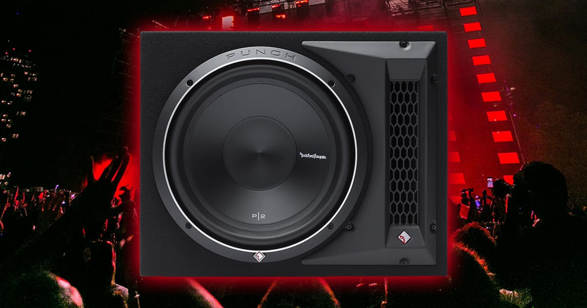
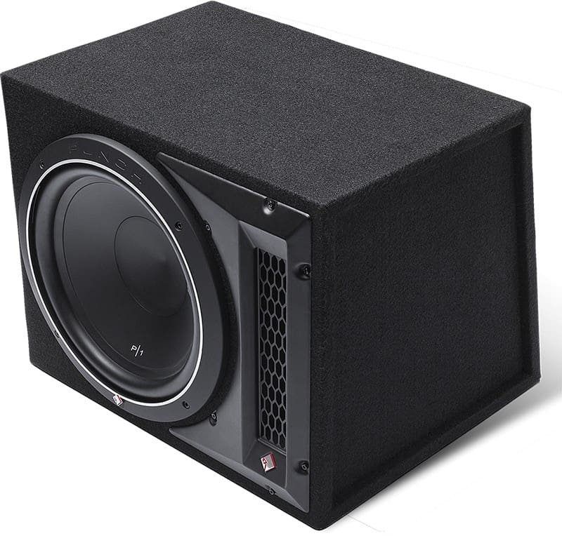
The P1-1X12 is a bass reflex (vented) subwoofer enclosure loaded with a single 12-inch P1S4-12 four-ohm subwoofer. The woofer and rectangular vent face forward on the enclosure, so you don’t have to worry about the proximity of vehicle trim panels changing the tuning frequency. This is an issue that enclosures with vents on the sides can suffer from.
Rockford Fosgate includes a trim panel for the enclosure’s front panel that serves three purposes. First, it features a mesh grille over the vent, which prevents your friends from putting candy wrappers in there. In our experience, it also keeps kids from putting their Hot Wheels cars in. Second, the trim piece’s tapered shape works as a radius at the vent opening to reduce wind chuffing and distortion. Finally, the trim piece’s matte finish and Diamond-R logo look cool.
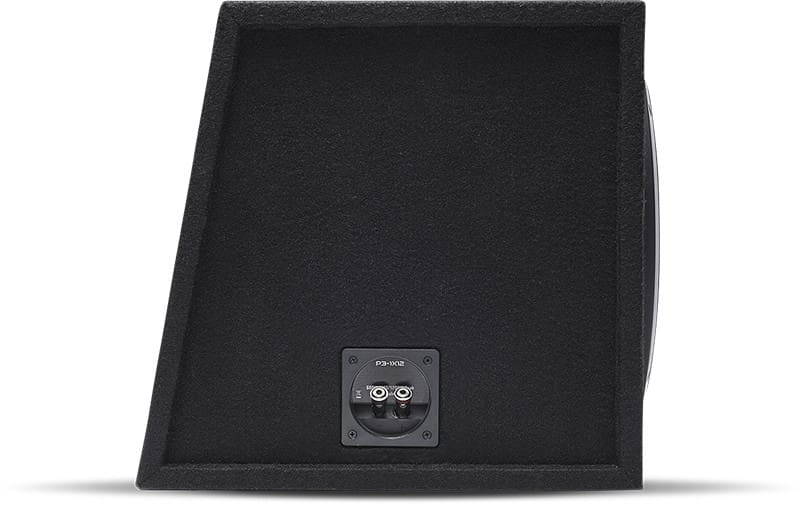
The enclosure is finished in a durable, high-density black “trunk liner”-style carpet that blends with most vehicle interiors.
Rockford Fosgate offers the P1G-12 mesh grille as an upgrade. Adding the grille is a wise choice if you carry cargo in the trunk. The woofer cone slapping into your groceries or sports equipment is a surefire way to cause damage.
P1-1X12 Subwoofer Enclosure Specifications
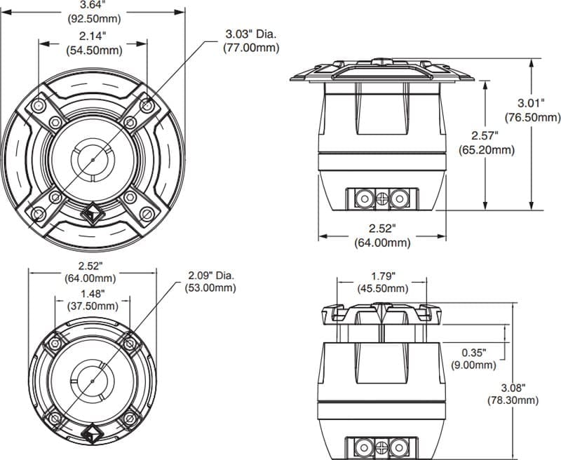
The Rockford Fosgate P1-1X12 enclosure measures 19.125 inches wide, 15.125 inches tall and 15.75 inches deep at the bottom. Its angled back panel fits tight against the seatbacks in your car or SUV. Wedge-style enclosures can save you several inches of storage space compared to enclosures with vertical back panels. This type of enclosure is more complicated to design and manufacture, but it’s a worthwhile investment in maximizing the usable space in your vehicle.
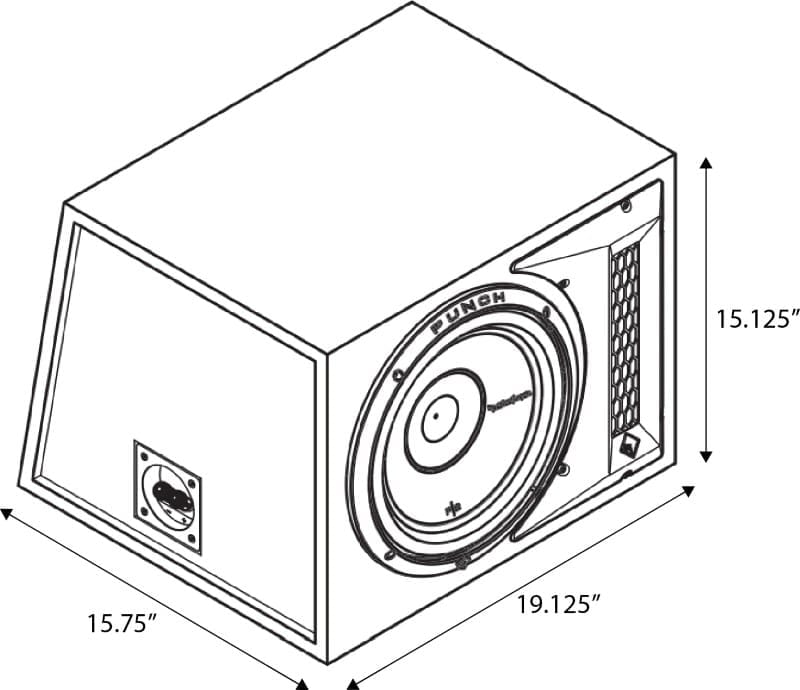
The enclosure is constructed from 5/8-inch MDF to balance weight and panel rigidity. Speaking of weight, the enclosure comes in at just under 40 pounds.
The P1S4-12 subwoofer has a single four-ohm voice coil rated for 250 watts continuous or 500 watts maximum. This makes the enclosure ideal for use with two- and four-channel amps in a bridged configuration. A solution like the P400X4 would be perfect, as it produces up to 200 watts from a pair of bridged channels. You can use the other pair of channels to power a set of component speakers in the front of the vehicle.
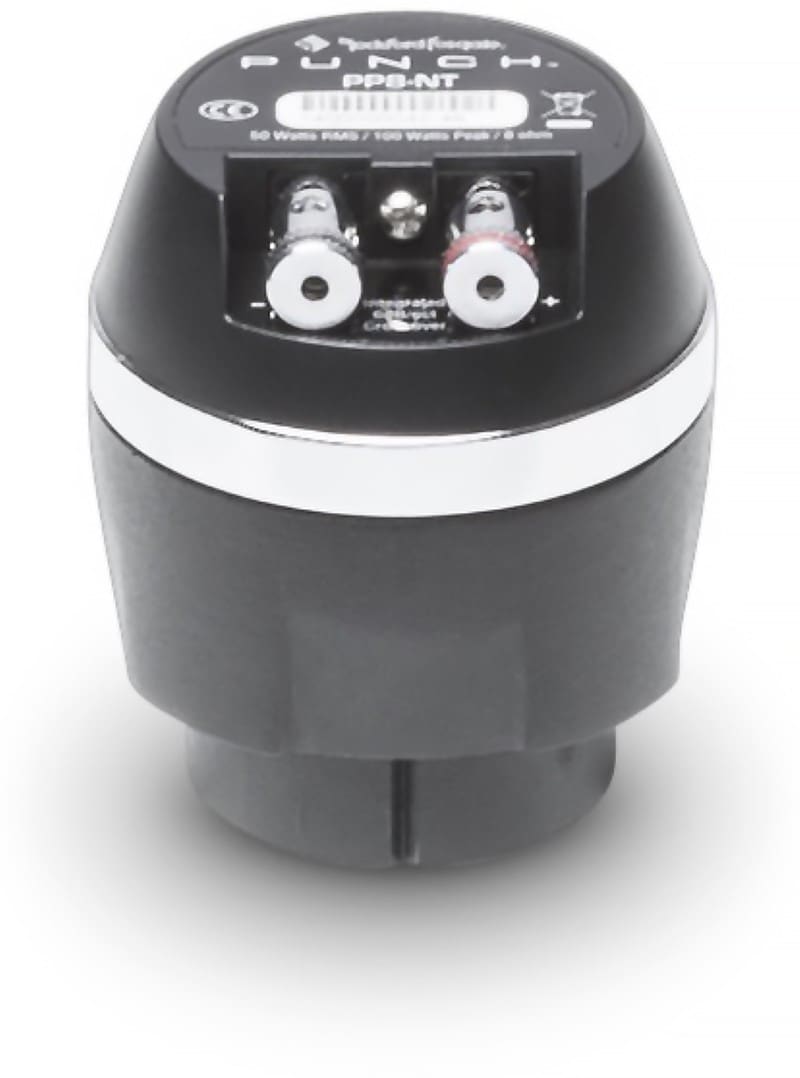
Electrical connections are handled by a custom-tooled terminal cup on the left side of the enclosure. The cup accepts 10-AWG speaker wire and features spring-loaded terminals to ensure a solid connection.
Punch Loaded Subwoofer Enclosure Family
Rockford Fosgate offers a complete line of subwoofer enclosures in the Punch family. There’s a single 10-inch version of this enclosure called the P1-1X10 and larger models with dual 12- and 10-inch subwoofers called the P1-2X12 and P1-2X10. If you want a solution that will play louder, then the P3-1X12 with a Punch P3 subwoofer rated at 600 watts continuous is an option. There are also P2- and P3-level dual subwoofer enclosures available. Your dealer can help you choose a model that fits your vehicle, performance goals and budget.
Upgrade Your Car Audio System with Rockford Fosgate Today!
We’ve said it dozens of times, but it bears repeating. The first and best upgrade you can make to your car stereo system is to add an aftermarket subwoofer. This applies even to higher-end factory-installed systems, as few will dedicate enough space to getting that deep, impactful bass that car audio fanatics expect.
When it’s time to bring your car audio system to life, visit a local authorized Rockford Fosgate retailer and ask about Punch Series loaded subwoofer enclosure solutions like this P1-1X12 and its counterparts. You can find an authorized retailer by visiting their website and using the locator tool. Be sure to check out Rockford Fosgate on Facebook, Instagram and YouTube to stay up to date with their latest product releases and the events they attend.
This article is written and produced by the team at www.BestCarAudio.com. Reproduction or use of any kind is prohibited without the express written permission of 1sixty8 media.