When it comes to subwoofer amplifiers from Rockford Fosgate, a few models stand out in the annals of car audio history: the Power 1000, the Power T15kW and the T2500-1bdCP. The latter is currently the flagship of the Power Series and is the most powerful subwoofer amplifier available from our friends in Tempe, Arizona. It’s a workhorse capable of impressive performance, so let’s check it out!
Rockford Fosgate T2500-1bdCP Features
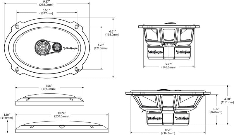
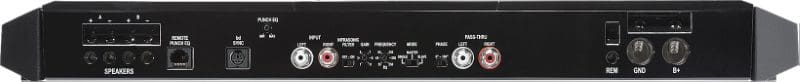
The T2500-1bdCP is a 2,500-watt subwoofer amplifier. It’s based on a large cast aluminum heatsink with a footprint of 8.14 inches in depth, 21.875 inches in width and a total height of 2.14 inches. All the power, signal and subwoofer connections are made along the front edge of the amplifier. A pair of massive 0-AWG terminals on the right side connect the amp to your battery bank, and two pair of speaker terminals on the left side will accept up to 8-AWG speaker wires.
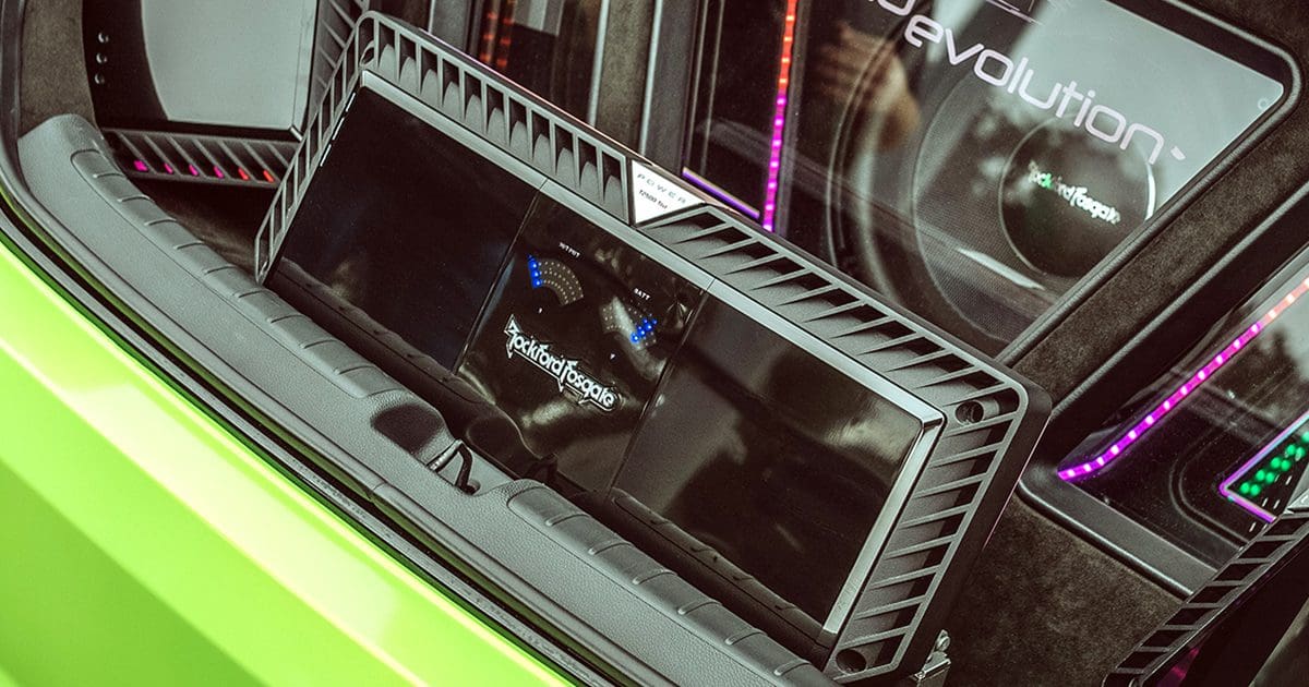
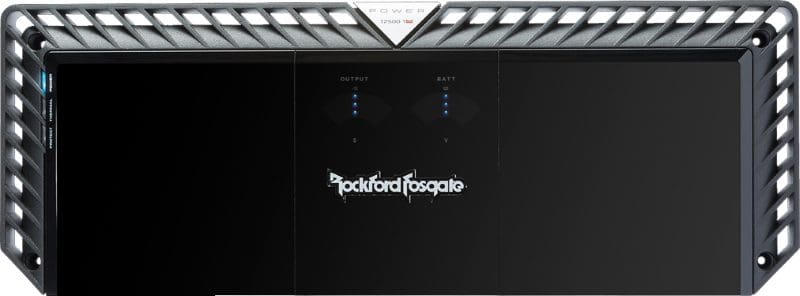
The center panel on top of the amplifier is home to a pair of LED-based level meters. The left-hand meter shows output power in 11 steps from idle to +2 dB (well into clipping). The right-hand meter displays battery voltage from 9 to 16 volts in 11 steps.
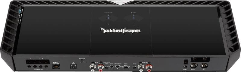
In the center of the side panel are the configuration controls. The amp will accept up to 4 volts of input on the RCA terminals. Of course, Rockford Fosgate has included balanced differential inputs on the RCA jacks to eliminate noise that might have been picked up by the RCA interconnects. The low-pass crossover is non-defeatable and offers -24 dB/octave attenuation with frequencies adjustable between 35 and 250 hertz. A selectable infrasonic filter applies a high-pass filter to the audio signal with a 12 dB/octave filter set to 28 hertz.
Of course, the amp includes the famous Punch EQ circuit that allows your installer to dial in up to 18 dB of boost at 45 hertz. An optional Remote PEQ module can be added to let the driver adjust the Punch EQ circuit from the front of the vehicle.
The amp features Rockford Fosgate’s BD output configuration that delivers excellent efficiency and sound quality. The Constant Power design helps ensure that the amp makes as much power as possible into various load impedances.
T2500-1bdCP Power Ratings
In terms of power production capabilities, the T2500-1bdCP is rated to produce 1,500 watts of output into a 4-ohm load and 2,500 watts into 2- and 1-ohm loads. Given our lab experience with Rockford Fosgate products, these numbers are likely underrated by about 10%.
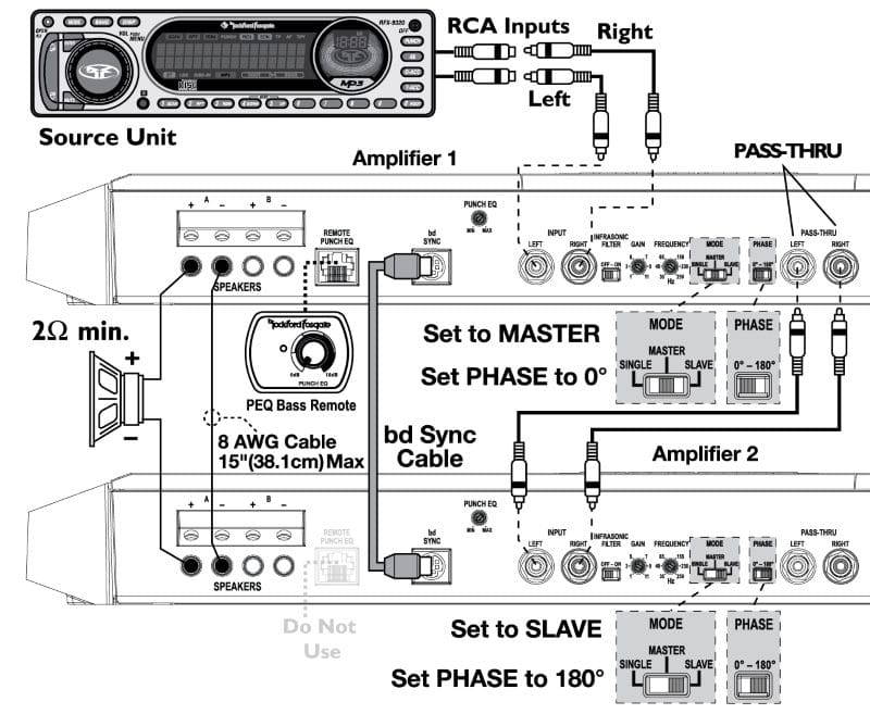
If that’s not enough, two of these amps can be strapped together using the optional bdSYNC2 cable to deliver 5,000 watts of power into a 4- or 2-ohm load. Voice coils, be warned! The amp also has a MasterSync mode that allows a single unit to drive an array of similar amplifiers with the same configuration settings. The RCA output jacks on the right side of the side panel are fundamental to making these features function. Uniquely, your installer can combine the bdSync and Master Sync modes to drive two subwoofers with 5,000 watts each using four amplifiers.
Smart car audio system designers will know that all amplifiers decrease in efficiency with decreases in load impedance. Rockford Fosgate rates the T2500-1bdCP as being 81.9% efficient at 4 ohms, 77.7% efficient at 2 ohms and 64.5% efficient when connected to a 1-ohm load. If you want to get the most bang for your buck in terms of battery and alternator capacity, a 2-ohm load makes these amps the happiest.
By way of sound quality specifications, Rockford Fosgate rates the amp as having a signal-to-noise ratio of at least 70 dB at a 1-watt output level. This is impressive for an amplifier with this much signal gain and capable of so much power. As with all amplifiers from Rockford Fosgate, all specifications comply with the ANSI/CTA-2006-C standard for car audio amplifier specifications.
Experience Bass Like Never Before with Rockford Fosgate
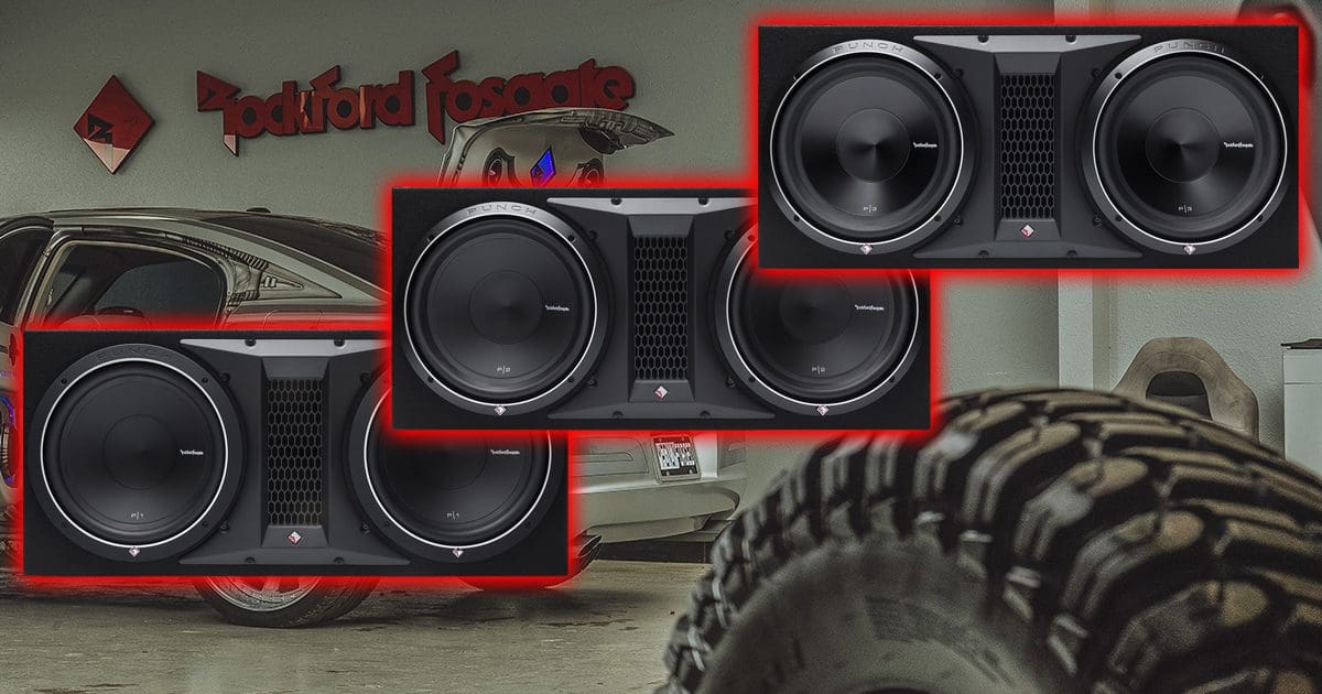
If you are after the ultimate high-end subwoofer system, drop by a local authorized Rockford Fosgate retailer and ask about an amplifier like the amazing Power Series T2500-1bdCP. You can match it with a few of the Power Series subwoofers or one of the outrageously cool T3S1-19 superwoofers. For more information about Rockford Fosgate’s Power Series products, visit their website. You can find an authorized retailer near you using their Dealer Locator. Don’t forget to follow them on Facebook, Instagram and YouTube to learn about their latest solutions for cars, boats, motorcycles and powersports applications.
This article is written and produced by the team at www.BestCarAudio.com. Reproduction or use of any kind is prohibited without the express written permission of 1sixty8 media.