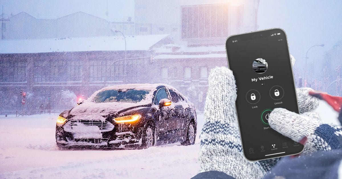
DroneMobile is undoubtedly one of the best solutions to control a remote car starter or security system in your car or truck. While the traditional key fob remote is a great backup, being able to send commands to your vehicle from almost anywhere using your smartphone is ultra-convenient. Better yet, your vehicle can use DroneMobile to send notifications to advise you if someone is tampering with it. Let’s take a close look at some of the features of this impressive vehicle control and communication system.
What Is DroneMobile?
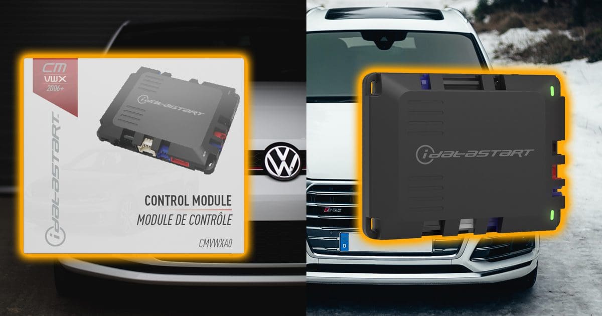
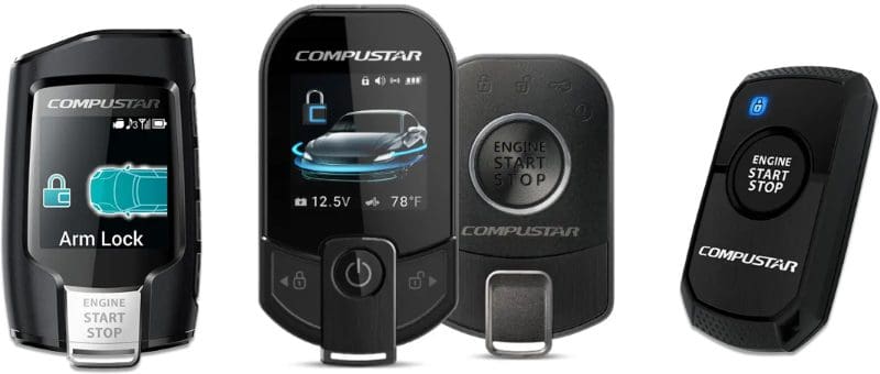
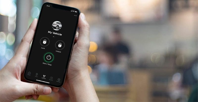
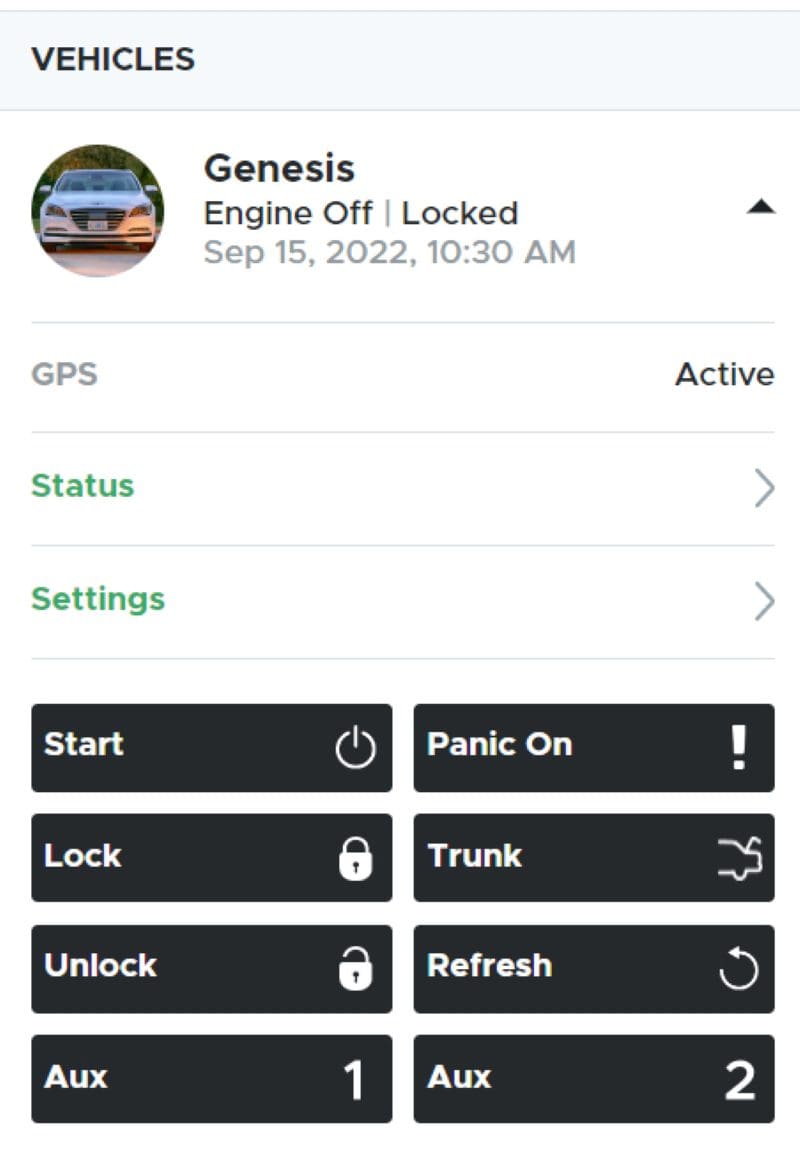
Telematics is the name given to solutions used to monitor the location and operation of cars and trucks using a telecommunication system. Suppose your vehicle has a Compustar, iDataStart or iDatalink remote car starter or security system. In that case, DroneMobile allows you to use your smartphone to send commands to the system controller in the vehicle instead of a traditional key fob. The system uses an application on your Android or Apple smartphone to talk to a DroneMobile computer module in your vehicle using the cellular data network. You can send unlock, lock or remote start commands with a simple touch of a button. Auxiliary outputs and trunk release control are also available. You can even activate the panic feature right from your phone.
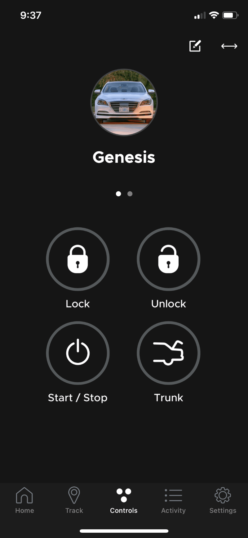
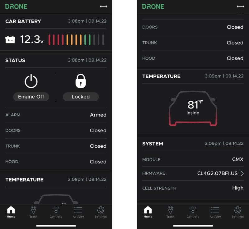
When you launch the DroneMobile app, you’ll initially see a status screen display for the last vehicle you sent commands to. Indeed, DroneMobile will work with any number of vehicles, making it perfect for a family with two cars or a company with a fleet of commercial vehicles. The status screen displays the battery voltage and the temperature inside your car or truck (if you have a temperature sensor built into your remote car starter). All of these functions are included with the Basic service package, which costs as little as $3.99 a month. That’s much less than most factory-installed telematics systems cost.
Vehicle Security Features
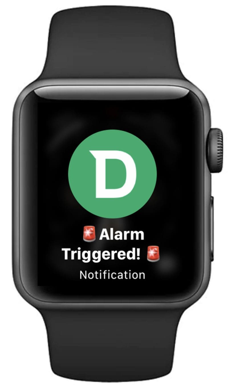
Another essential feature of DroneMobile is its security features. If you have a Compustar car alarm or have added the DAS or DAS-II sensor to a Compustar remote car starter, then alerts from the alarm will show up on your phone as a notification. If you have installed the DroneMobile app on your smartwatch, the notifications will also show up there.
Another feature included in the Premium and higher packages is towing alerts. If your vehicle is moved without the ignition being turned on, you’ll get an instant notification on your smartphone. If you have a luxury or exotic vehicle and are concerned that someone might tow it away in the middle of the night, this feature is a perfect way to protect your pride and joy.
Find and Track Your Vehicle or Fleet
If you opt for the Premium service plan, you can access a full suite of GPS-based functions and warnings. When you log into the app, DroneMobile will show you exactly where your vehicle is located on Apple or Google maps. Tapping on the map screen will enlarge the map and show you the engine status (off or running); if the vehicle is moving, it will display how fast it’s traveling. This feature is quite handy if you share your car or truck with a family member.
You can also configure GPS-based alerts and notifications. Speed Monitoring will notify you if the vehicle exceeds a predefined limit. Likewise, you can set curfew hours and receive a notification if the vehicle is started during that time. These features are excellent for business owners with a fleet of vehicles.
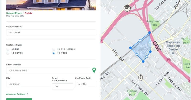
The Premium plan also includes user-configurable Point of Interest and geofence warnings. If one of your kids borrows the family vehicle to go to work, you can configure a geofence around the location and receive a notification when they arrive and when they leave. This is also an excellent feature for company vehicles that are intended for use in specific areas.
The Premium service plan will also track how far the vehicle has been driven to let you know when it’s time for service and maintenance. Should the computer in your car or truck produce a check engine light or error code, DroneMobile can forward that information to you.
Advanced GPS Features Are Great for Business
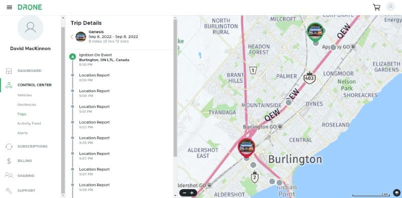
The DroneMobile Premium Plus and Ultimate service plans add detailed breadcrumb trails and turn-by-turn tracking. If you use your vehicle for work, the system will log each trip. You can log into the DroneMobile website to generate travel reports for your expenses. That information is stored for six months, so there is lots of time to create reports for income tax purposes.
High-Speed Communication
One complaint we hear from people using factory-installed smartphone control systems is that they seem to take forever to send commands from the smartphone app to the vehicle. We’ve heard from many people that the process can take 30 to 60 seconds. DroneMobile modules are built using LTE-based cellular communication radios, and the authentication database is hosted by Amazon Web Services (AWS). The result is a system that works with lightning-quick speed. In most cases, commands from your phone or watch are received and executed by the vehicle in two to three seconds. You’ll get confirmation back to the app that whatever command you’ve requested has been completed in the same blazing-fast time.
Ready When You Are
Compustar bundles a Drone X1 module with most of its premium two-way remote-control systems. New users are provided a 30-day Premium trial to experiment with the system’s features. An important consideration is that you can activate DroneMobile as you need it. If you don’t need to remote start your vehicle in the summer and only use the system in the winter, you can pay for service from December to March. Should your vehicle be stolen or you lock your keys inside and need access, you can activate the subscription and use the tracking or unlock the doors in a few minutes. You can even use DroneMobile from a desktop computer connected to the internet by visiting the DroneMobile website. One of our co-workers managed to lock his keys and phone in his truck. He used a computer at the restaurant he was dining at to log into the website and send an unlock command to the vehicle. The whole process took only a few minutes. You can even log into the dronemobile.com website using the web browser on a smartphone or tablet. As long as you have internet access, you are connected.
DroneMobile – The Ultimate Vehicle Control and Monitoring System
If you want to communicate with the remote car starter or security system in your car or truck from almost anywhere in the country, visit a local authorized Compustar or iDataStart retailer and ask about adding DroneMobile. Once you’re used to its speed and convenience, you’ll wonder how you lived without it.
This article is written and produced by the team at www.BestCarAudio.com. Reproduction or use of any kind is prohibited without the express written permission of 1sixty8 media.