 Paper maps used to be the only way of planning route navigation. Before you, or perhaps your parents, set out on vacation, you would pick up maps for each state or province you planned to drive through, lay them out on the kitchen or dining room table, and highlight the route to take.
The problem with maps is that someone has to read them, and trying to read a map while driving is quite dangerous. Automakers realized that maybe technology could be used to make driving safer. This concept was the birth of the navigation system.
Through the 1980s, Toyota and Mazda worked on several different navigation systems for their cars. Some of these early navigation systems used digitized paper maps. In the 1990s, Mazda introduced the first GPS-based navigation system. Nowadays, most vehicles sold in North America have the option of navigation.
Navigation System Hardware
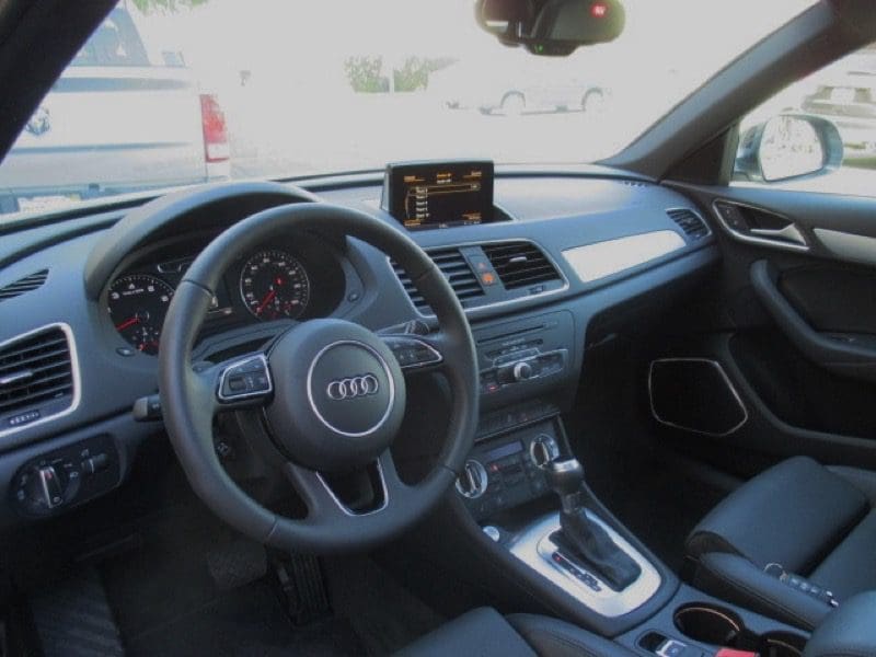
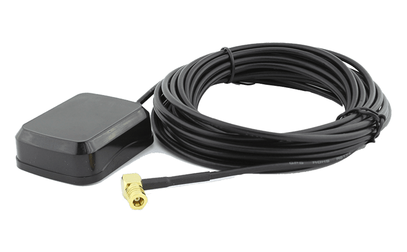 Modern navigation systems have four key components. The first is a computer. This computer runs the navigation software that plans the route you have requested, tells you when to turn and advises you when you arrive. The second key component is the maps used with the navigation software. Two companies offer these maps, which are licensed to the end-user. The third component is the GPS receiver module and antenna. The GPS receiver lets the navigation system know where you are, and where you are headed. Finally, there is an interface. The interface is usually a touchscreen of some kind. The interface displays the maps and accepts the input of information to plan the route. Information can be typed on a touchscreen or spoken to the software and converted to text.
What is GPS?
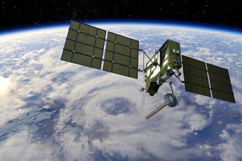 GPS stands for Global Positioning System. The U.S. Department of Defense created the technology in 1975 and it was fully functional by 1995. The purpose of the system was to provide accurate location, speed and altitude data anywhere on the planet. The GPS system comprises about 30 satellites that orbit the Earth. Each one transmits a uniquely coded signal with a very accurate time stamp. The GPS receiver can, once it has acquired signals from several satellites, triangulate its location by comparing the difference in arrival time of each signal. The GPS system most of us are used to is called Navstar, and it is operated and maintained by the U.S. Air Force Space Command.
Many consumers refer to a Portable Navigation System (PNS) or in-dash navigation system as a GPS. While this term has become accepted, GPS is just one key component of a navigation system.
Not surprisingly, there is more than one GPS system in use globally. Russia operates a system called GLONASS, India has IRNSS, the Chinese have BeiDou-2 and the Europeans have Galileo. Some GPS receivers can capture information from multiple systems to improve accuracy. An example would be a radio-controlled camera drone – these use GLONASS and Navstar to provide more resolution regarding their position.
The signal sent to the navigation computer by the navigation receiver includes the longitude, latitude, heading (the direction you are traveling), altitude, velocity and the current time.
What are Navigation Maps?
Knowing where you are on the planet is great. The real key to a navigation system is its maps. Maps are available from one of two companies: TomTom, which purchased TeleAtlas in 2007, and Nokia, which purchased Navteq in 2008.
 Maps are databases of roads stored as vectors. A vector is a line between two points. In the case of navigation road maps, the end points of the lines (or roads) are GPS coordinates. Most navigation map information contains additional information such as house numbers. If you have every wondered why some house or building addresses are off by a little bit, the reason is based on how addresses are stored. At one end of a street, or section of road, the map data contains the beginning house number. The other end of the street has the ending house number. Navigation systems spread out the difference between the two house numbers evenly along the length of the street. This predicted location does not always match reality because of geography – or pure randomness, based on the whim of the local municipal building department.
Navigation systems are useless without maps. They couldn’t plan routes or give directions. You are, quite literally, at the mercy of the quality and accuracy of the maps you own.
Working in conjunction with the map database is a Points of Interest (also known as POI) database. A POI database contains information about businesses and landmarks, and often includes a phone number. Depending on your navigation system, you may have as few as 1.5 million points of interest or as many as 11 million. The manufacturer decides how much they are willing to spend on this information. If your navigation system can search for gas stations, hotels, restaurants or hospitals, then the map data includes a POI database.
Some of the very first navigation systems used analog tape to store map and POI data. Yes – analog, magnetic tape! From that point, we moved to CD-ROM, DVD-ROM, hard disk drives and flash memory. The latest systems are based on smartphones and don’t have the map data permanently stored onboard – it’s all downloaded over the air, using a cellular connection in real time.
Modern Navigation System Features
 Modern navigation systems are amazing tools to help you travel safely and efficiently. These systems use extremely complex and proprietary algorithms to decide the best route between the starting and ending points of your route. The most basic of navigation software takes into consideration the size of the road (number of lanes and, if available, speed limit) and the direction of the turns you may have to make to complete the route. Navigation software companies are very protective of their route creation algorithms.
Modern navigation systems can accept real-time information to make route planning more accurate and efficient. The first upgrade was including traffic flow information. Many systems used FM antennae to capture traffic flow information that was broadcast in major urban areas. This technology is called RDS-TMC traffic, since the information was coded into the same frequency space as FM radio RDS information. Newer systems capture this traffic flow and accident information through the SiriusXM receiver. You do need a subscription to SiriusXM Traffic and, of course, supporting hardware in your vehicle to makes this work.
Apple CarPlay and Android Auto
If you have a vehicle with Apple CarPlay or Android Auto, your smartphone becomes an integral part of your navigation solution. Apple or Google stores map information and downloads it in real time through your smartphone’s data plan. The beauty of this solution is that you never, ever have to pay for map updates – the information is always being updated.
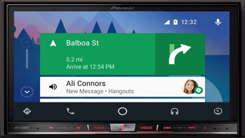 Apple Maps and Google Maps both offer turn-by-turn navigation solutions that use each brand’s advanced voice recognition software. All you have to do is press a button and ask the system to take you to an address.
CarPlay and Android Auto navigation has the benefit of being able to acquire Point of Interest information directly from the Internet. If a new company opens and registers itself with Apple and Google, you can search for it right away.
One drawback of CarPlay and Android Auto is that the maps aren’t stored on the phone or in the vehicle. If you are traveling to another country, your cellular provider will charge roaming fees. (You can get roaming data plans to help minimize the cost, so that’s not a huge deal, but it has to be considered before you buy.) Another consideration is that these systems are constantly downloading map information. If you happen to have a cellular data plan with very limited bandwidth, this could eventually cost some money in data overage charges. These are not show-stoppers, just considerations.
Google Waze
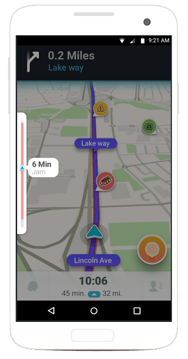 One very popular navigation application used by people who live in high-traffic areas like Los Angeles, Toronto, San Francisco, Seattle, Honolulu, New Orleans or Chicago is called Waze. This application is available for iPhone and Android phones for free. The beauty of Waze is that other users provide traffic flow information, including detours, accidents and warnings for potholes, weather or even animals on the road. Waze offers crowd-sourced traffic information at its finest. Google purchased Waze in June of 2013 for $1.3 billion. If you run the risk of getting stuck in a traffic jam, try Waze; it’s quite impressive.
Using any navigation solution has its perils. If your co-pilot is reading directions from a paper map, or you are trying to drive while listening to voice prompts from a navigation system, there is always the risk of making an error while turning, merging or exiting. Always be careful when navigating and heed the rules of the road at all times.
If you are in the market for a navigation solution for your vehicle, visit your local mobile electronics specialist. They have many different solutions depending on the vehicle you drive. Some systems replace the factory radio, some work with it and some operate separately from it. They can show you the options for your vehicle.
This article is written and produced by the team at www.BestCarAudio.com. Reproduction or use of any kind is prohibited without the express written permission of 1sixty8 media.


 As we move toward the end of our discussion of car audio electrical theory, we need to talk about capacitance and inductance and how the characteristics of those phenomena interact with AC and DC signals. There’s no doubt that these are advanced concepts, but even a basic understanding of how capacitors and inductors work is fundamental to a thorough understanding of
 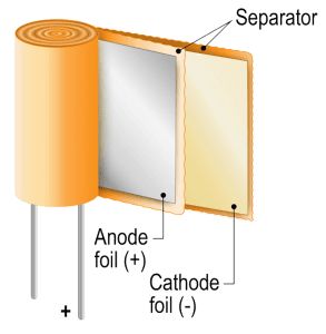 A capacitor is a two-terminal electronic component that stores energy. Capacitors are made of two metallic plates that are separated by an electrical insulator. When we apply a voltage to one terminal of the capacitor, the electrons on one plate will impose a force on the opposite plate to create an opposite charge. The result is that the plates have equal and opposite charges and thus, maintain an electric field. Because the plates in a capacitor are very close together, they can store a large amount of energy for their overall size.
 Capacitors are, at their most basic function, a device that stores a microscopic magnetic field between its plates. When we apply a DC voltage to a discharged capacitor, it appears as a short circuit for an instant as the magnetic and electric fields start to form between its plates. As the capacitor starts to store energy, it increases in effective resistance, and the amount of current flowing through the device is reduced. Once the capacitor has equalized with the supply voltage, almost no current passes through the device.
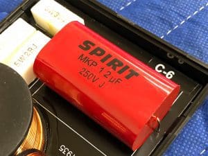 In alternating current circuits, capacitors take on an interesting phenomenon of “virtual resistance.” As we know, capacitors don’t like to change voltage, yet an AC signal is one that is defined as ever-changing. Depending on the relationship between the capacitor value and the frequency of the AC signal, some amount of the current is allowed to pass through the cap.
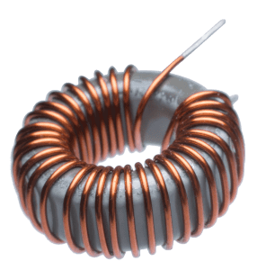 In the simplest of terms, an inductor is a coil of wire that creates a magnetic field based on the amount of current flowing through it. Many inductors feature iron cores to increase the intensity of the magnetic field. Where a capacitor resists changes in voltage, an inductor resists changes in current flow. We know from our previous article on magnetism that current flowing through a conductor creates a magnetic field around that conductor. If we wrap the conductor in a loop, the proximity of the loops to one another intensifies the magnetic field.
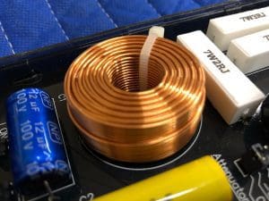 In most applications, we don’t want inductors in a 12V DC circuit because they resist changes in current flow. For a variable load such as an amplifier, a large amount of inductance in the supply wiring would result in an unstable supply voltage as the current requirements change.